
Gear Milling for Large Mechanical Spare Parts
Gear milling is a proven machining method for producing spur gear teeth, especially suited for large, non-standard mechanical spare parts used in heavy industry, mining, energy, and marine applications. Unlike high-volume processes like hobbing, which are optimized for mass production, gear milling leverages universal milling machines and form cutters, offering unmatched flexibility—particularly in custom, low-volume, or emergency repair scenarios. This adaptability makes it an ideal solution when dedicated tooling, long lead times, or specialized equipment are not feasible.
Gear Milling
Challenges in Machining Large Non-Standard Gears
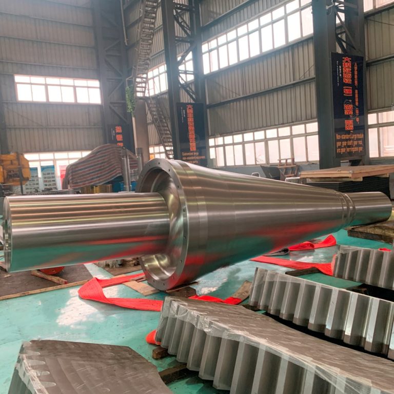
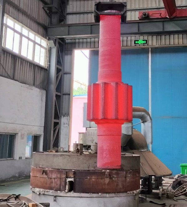
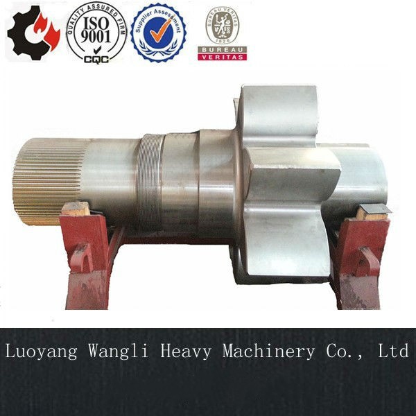
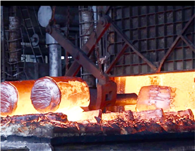
These components often feature large modules (m > 10 mm), diameters exceeding 1 meter, low tooth counts, segment designs, or heat-treated alloy materials. Given their large size and complex geometries, coupled with the fact that they are typically required in single-unit or very small batches, conventional gear manufacturing methods—such as hobbing or shaping—become not only technically challenging but also economically unviable. As a result, these factors make such processes often impractical or cost-prohibitive, thereby creating a need for more flexible and adaptable machining solutions like gear milling.
Why Gear Milling Excels
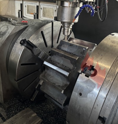
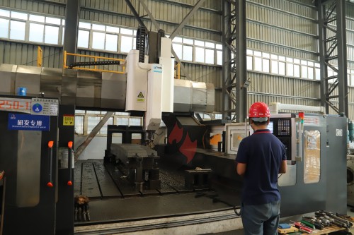
- Equipment Flexibility: Utilizes standard milling machines, eliminating the need for dedicated gear-cutting equipment—making it accessible even in general-purpose machine shops.
- Handles Complex Geometries: Moreover, it excels in machining non-standard configurations such as segment gears, partial gears, eccentric designs, and localized tooth repairs, where conventional methods fall short.
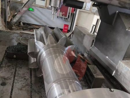
- Supports Large Modules: In addition, gear milling is well-suited for large-module gears (m > 10), as custom disc cutters are easier and more cost-effective to produce compared to large, specialized hobs.
- Fast Turnaround: Critically, this process enables rapid in-house or on-site repairs, significantly reducing lead times and minimizing costly equipment downtime.
- Low Investment: Finally, it requires minimal capital investment, making it a cost-effective solution for small workshops, maintenance teams, or emergency production scenarios.
Precision & Best Practices
While typical accuracy ranges from ISO 1328 Class 9–10, precision can be improved by:
- First, use high-accuracy dividing heads or CNC rotary tables to minimize indexing errors and ensure consistent tooth spacing.
- Next, employ carbide cutters, which offer superior wear resistance and enable higher cutting speeds, resulting in improved surface finish.
- Then, perform both rough and finish milling passes to control dimensional accuracy and reduce residual stresses on the tooth profile.
- Finally, carry out deburring, chamfering, and optional hand-finishing to remove sharp edges and optimize tooth contact, ensuring smoother meshing and quieter operation.
In conclusion, gear milling remains a practical, flexible, and economical solution for manufacturing and repairing large non-standard mechanical spare parts. Thanks to its high adaptability, it has become indispensable for emergency repairs, custom designs, and low-volume production—especially in environments where rapid response and minimal downtime are critical. As a result, it plays a vital role in ensuring operational continuity and cost efficiency across heavy industries such as mining, energy, and heavy machinery.
1. Types of Gear Milling and Cutter Selection
- Disc Gear Cutters: Most common; grouped by module and tooth count (e.g., 8-cutter set) for standard involute profiles.
- Shank-Type Cutters: Used for large modules, wide tooth spaces, or roughing internal gears.
- Form Cutters vs. Module Cutters: Explain selection criteria based on accuracy and application.
2. Indexing Head Usage and Indexing Calculations
- Simple Indexing Formula: A fundamental method used in gear milling is simple indexing, where the required crank rotations are calculated using the formula:
Crank Turns=40ZCrank Turns=Z40
(applicable for a standard 40:1 dividing head). This straightforward calculation allows for quick setup when machining gears with common tooth counts. - Differential Indexing: However, when the tooth count is a prime number or otherwise incompatible with simple indexing, differential indexing must be employed. This more advanced technique uses a gear train to compensate for fractional crank movements, enabling precise indexing for any number of teeth.
- Indexing Reference Table: To simplify setup and reduce calculation errors, an indexing reference table is often used in practice. Such a table lists common tooth counts alongside their corresponding crank turns and hole circle settings, thereby improving efficiency and accuracy on the shop floor.
3. Material Compatibility and Recommended Cutting Parameters
Include a cutting parameter reference table:
| Material | Module Range | Cutter Type | Cutting Speed (m/min) | Feed per Tooth (mm) |
|---|---|---|---|---|
| 45# Steel | m=3–10 | HSS Disc Cutter | 20–30 | 0.1–0.2 |
| 40Cr (Quenched) | m=6–16 | Carbide Cutter | 40–60 | 0.08–0.15 |
| Cast Steel/Iron | m=5–12 | Coated HSS or Carbide | 25–35 | 0.15–0.25 |
4. Safety Operating Guidelines
- Inspect cutters for cracks or wear before installation
- Securely clamp workpieces to prevent ejection during rotation
- Never remove chips by hand during operation
- Use coolant to prevent thermal deformation
Contact us

.jpg)
-768x768.jpg)