
Straight Bevel Gear: Concepts and Operation
1.What is a Straight Bevel Gear?
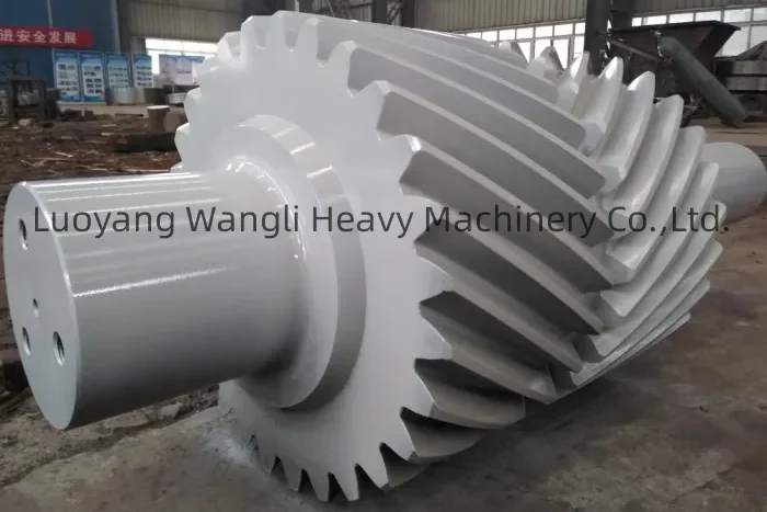
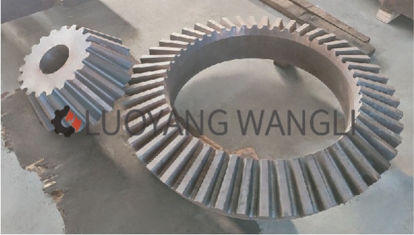
In the intricate world of mechanical power transmission, few components are as elegantly simple and functionally crucial as the Straight Bevel Gear. This mechanical workhorse is the fundamental solution for one specific task: efficiently transmitting torque and changing the direction of rotation between two shafts that intersect. Commonly found in everything from the humble hand drill to the complex differential of a heavy-duty truck, the Straight Bevel Gear is characterized by its straight, tapered teeth that point directly toward the apex of an imaginary cone. Its design prioritizes simplicity, reliability, and cost-effectiveness, making it a go-to choice for a vast range of moderate-speed applications.
2.Deconstructing the Fundamental Concepts of a Straight Bevel Gear
To fully appreciate how a Straight Bevel Gear functions, one must first become familiar with its geometry and terminology. Unlike parallel-axis gears, its operation is based on conical surfaces, which introduces unique design considerations.
2.1.Core Geometry: More Than Just a Cone
At its heart, a Straight Bevel Gear is a conical disk with teeth carved onto its tapered face. The geometry is designed so that if the gears were to be extended inward, all their teeth would converge at a common apex point.
2.1.1.The Pitch Cone and Cone Angle
The most critical imaginary element is the Pitch Cone. This cone represents the ideal surface where two meshing gears would roll together without slipping, akin to two friction cones. The cone angle defines the relationship between the two shafts. In a 90-degree shaft configuration, the sum of the two pitch angles of the mating gears equals 90 degrees.
2.1.2.The Gear Axis and Shaft Angle
The Gear Axis is the central line of the shaft on which the gear is mounted. The Shaft Angle is the angle at which these two axes intersect. While 90 degrees is the most common, a Straight Bevel Gear set can be designed for virtually any intersecting shaft angle.
2.1.3.Face Width and Taper
The teeth are not rectangular; they are tapered, being taller and wider at the outer end (the heel) than at the inner end (the toe). This taper is essential to maintain a uniform clearance and ensure proper tooth engagement throughout the face width.
2.2. Essential Terminology for Understanding
2.1.Pinion and Gear (or Crown Gear)
In any gear pair, the smaller driver is called the Pinion, and the larger driven gear is simply the Gear. In a bevel gear set with a 1:1 ratio, they are identical. A specific type is the Crown Gear, which has a pitch angle of 90 degrees, resembling a flat crown, with its teeth pointing radially outward.
2.2.The Back Cone and Virtual Spur Gear
This is a crucial conceptual tool for engineers. The Back Cone is an imaginary cone perpendicular to the pitch cone. Its elements are used to define a “virtual spur gear.” This allows designers to use the more straightforward calculations and standard tooth profiles of spur gears to approximate the design and strength of the more complex Straight Bevel Gear, significantly simplifying the manufacturing process.
3.The Working Principles: How a Straight Bevel Gear Transmits Power
3.1.The process of power transmission is a continuous cycle of force application:
3.1.1.Input Initiation: Rotational motion and torque are applied to the input shaft, which is rigidly connected to the driving Straight Bevel Gear (typically the pinion).
3.1.2.Tooth Engagement and Force Transfer: As the pinion rotates, the leading flank (side) of one of its teeth comes into direct contact with the corresponding flank of a tooth on the driven gear. This contact is not a pure rolling motion; it involves a significant amount of sliding friction as the teeth engage and disengage.
3.1.3.Directional Change via Inclined Plane Action: Each tooth can be thought of as a meticulously crafted inclined plane. The force from the driving tooth is applied at an angle to the driven gear’s axis. This angular force application is what generates the torque around the driven gear’s axis, effectively changing the direction of the power flow.
3.1.4.Output and Continuous Cycle: The applied force causes the driven gear to rotate about its own axis. As one pair of teeth disengages, the next pair is already making contact, ensuring a smooth and continuous transfer of power. The velocity ratio is determined by the ratio of the number of teeth on the two gears.
3.2. The Dynamics of Straight Teeth Engagement
The choice of a straight-tooth profile defines the performance characteristics of the Straight Bevel Gear.
3.2.1.Sliding Contact and Its Implications: The primary characteristic of the engagement is the high degree of sliding contact between the tooth flanks. This sliding action results in higher friction losses, increased heat generation, and a tendency to be noisier, especially at high rotational speeds. The “chatter” or “whine” often associated with older car differentials when cornering is a classic sound of Straight Bevel Gears in action.
3.2.2.Simplicity and Ease of Manufacturing: The significant advantage of the straight-tooth design is its manufacturability. These gears can be produced using relatively simple gear-generating machines, much like standard spur gears. This ease of production makes them significantly more economical than their spiral or hypoid counterparts.
4. Advantages and Limitations: A Balanced Perspective
Like any engineering component, the Straight Bevel Gear has a specific set of strengths and weaknesses that determine its ideal application space.
4.1.Key Advantages:
Cost-Effectiveness: They are generally the least expensive type of bevel gear to produce, making them ideal for cost-sensitive applications.
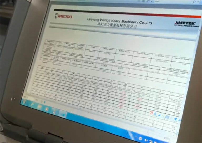
Ease of Manufacture and Inspection: The straight teeth allow for straightforward machining processes and simpler quality control measurements.
No Axial Thrust (in theory): Under ideal conditions with perfect geometry, straight bevel gears do not generate significant axial thrust, simplifying bearing selection. However, in real-world applications, some thrust is present and must be accounted for.
High Efficiency at Low-Moderate Speeds: For applications not requiring high speeds, they offer excellent power transmission efficiency.
4.2.Inherent Limitations:
Noise and Vibration: The abrupt engagement of the straight teeth makes them louder and more prone to vibration than spiral bevel gears.
Lower Load Capacity: For a given size, they cannot handle as much torque or load as a spiral bevel gear, whose curved teeth provide a smoother, more gradual engagement.
Unsuitability for High-Speed Applications: The noise, vibration, and heat generated from sliding friction make them a poor choice for high-RPM machinery.
5.Material Selection and Manufacturing Processes
The performance and lifespan of a Straight Bevel Gear are heavily influenced by the materials used and how they are made.
Common Materials: Choices range from cost-effective plastics (acetal, nylon) for light-load, quiet applications, to various steels (carbon, alloy, case-hardened) for high-strength and durability in industrial settings. Cast iron and bronze are also used for specific wear-resistance or non-sparking requirements.
Manufacturing Techniques: Common methods include gear shaping (using a reciprocating cutter), gear planning, and bevel gear milling. For high-volume production, specialized forging processes are employed to create near-net-shape gear blanks that require minimal finishing.
6.Diverse Industrial Applications of Straight Bevel Gears
The Straight Bevel Gear remains indispensable across numerous industries. Its reliability and simplicity ensure its continued use in:
Automotive Differentials: While many modern cars use spiral bevel gears for quietness, Straight Bevel Gears are still found in some differentials, especially in older models and heavy machinery where ultimate quietness is not the primary concern.
Power Tools: Drills, saws, and sanders often use Straight Bevel Gears to transfer power from the motor to the output shaft at a 90-degree angle.
Industrial Machinery: They are widely used in conveyors, packaging machines, printing presses, and other equipment where a reliable right-angle power turn is needed.
Marine Propulsion: Inboard boat engines frequently use Straight Bevel Gear sets in the transmission to direct power to the propeller shaft.
Agricultural Equipment: From tractors to combines, the robust and straightforward nature of the Straight Bevel Gear makes it suitable for demanding agricultural environments。
Application Scenarios of Straight Bevel Gears in Heavy Machinery
| Application Field | Specific Equipment Examples | Core Function & Value | Company Product Advantages |
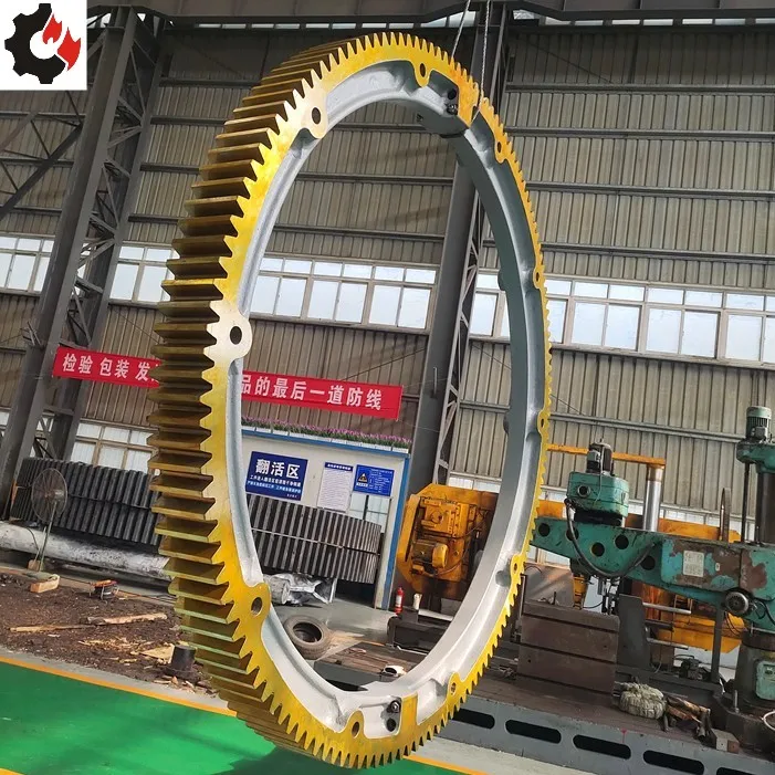
| Metallurgical Equipment | Steel Rolling Mill, Straightening Machine, Continuous Casting Machine | Achieve 90-degree power transmission for rolling mills in confined spaces, withstand massive impact loads. Simple structure, high reliability, easy maintenance. | Provide gears made of alloy steel with deep carburizing and quenching treatment to ensure high wear resistance and impact resistance. |
| Mining Machinery | Ball Mill, Crusher, Mine Hoist | Core transmission components for driving drum rotation or lifting heavy loads. Exceptional durability in harsh dusty environments. | Focus on large module gear manufacturing with high-strength teeth to meet long-cycle, heavy-load operation demands in mining equipment. |
| Heavy Lifting & Transportation | Port Gantry Crane, Tower Crane, Crawler Crane | Change power direction in crane rotation and amplitude mechanisms for precise boom rotation and elevation. | Gears undergo precision pairing and grinding to ensure smooth transmission and low noise, meeting heavy equipment control accuracy requirements. |
| Building Materials & Cement | Rotary Kiln, Tube Mill, Roller Press | Drive massive kiln/mill drums at low speed. Gears must withstand extreme thermal and mechanical loads. | Provide large cast/forged blank supply capabilities and high-temperature-resistant tooth profile design for stability in cement plant high-temperature conditions. |
| Shipbuilding & Heavy Industry | Ship Propeller, Deck Crane, Rudder Motor | In propulsion systems, transmit 90-degree power to propeller shaft; provide reliable power steering for deck machinery. | Products comply with ship classification society certifications (CCS, DNV, ABS), offering excellent corrosion resistance and high reliability. |
| Power & Energy | Hydro Turbine, Wind Turbine Yaw System | Used in hydropower station governors; adjust nacelle direction in wind turbines to align with wind. | Provide customized tooth profile optimization to reduce meshing friction, enhancing transmission efficiency in large-megawatt wind power and other high-end equipment. |
7.The Enduring Legacy of the Straight Bevel Gear
While advancements in gear technology have led to quieter and stronger alternatives for high-performance applications, the Straight Bevel Gear continues to hold a vital and irreplaceable position in the world of mechanics. Its unparalleled combination of simplicity, cost-efficiency, and reliability for low-to-moderate speed power transmission ensures that this classic component will remain a fundamental building block in countless machines, from the everyday to the industrial, for the foreseeable future. Understanding its concepts, principles, and ideal use cases is essential for any engineer or enthusiast working with mechanical systems.
Feel free to contact us for more information or assistance.
Our LinkedIn Page

-768x768.jpg)