
How to Find Gear Ratio: A Practical Guide for Mining Equipment Maintenance
In the demanding world of mining operations, where heavy-duty machinery operates under extreme loads, dust, and continuous duty cycles, understanding mechanical transmission is essential. One of the most critical parameters in ensuring reliable performance of mining equipment is the gear ratio.
Whether you’re maintaining a conveyor drive, servicing a crusher gearbox, or replacing components in a ball mill system, knowing how to find gear ratio accurately can prevent unexpected downtime, reduce mechanical stress, and ensure the motor is properly matched to the load.
This guide provides field-tested methods to find gear ratio specifically for mining applications—no robots, no automotive examples—just practical solutions used by maintenance teams in real mining environments.
.png)
Testing
Why Gear Ratio Matters in Mining Equipment
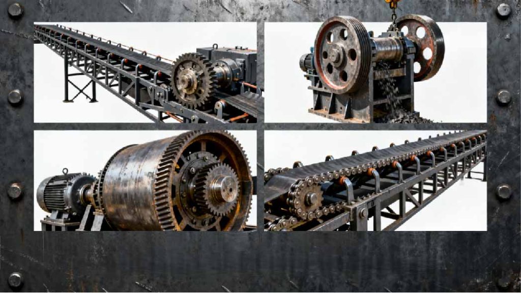
Mining machinery such as belt conveyors, jaw crushers, grinding mills, scraper conveyors, and hoists rely on robust gearboxes to convert high-speed motor output into high-torque, low-speed motion.
The directly affects:
1.Starting torque and ability to handle shock loads
2.Power transmission efficiency
3.Motor loading and energy use
4.Rate of gear and bearing wear
An incorrect or mismatched gear ratio can lead to:
1.Overheating gearboxes
2.Belt slippage or chain failure
3.Motor tripping due to overload
4.Reduced throughput and unplanned stoppages
How to Find Gear Ratio: 3 Field-Validated Methods
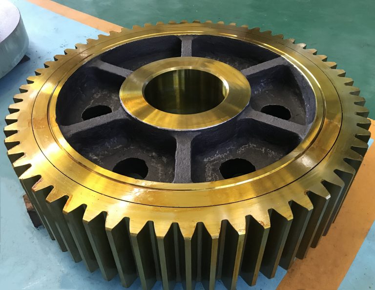
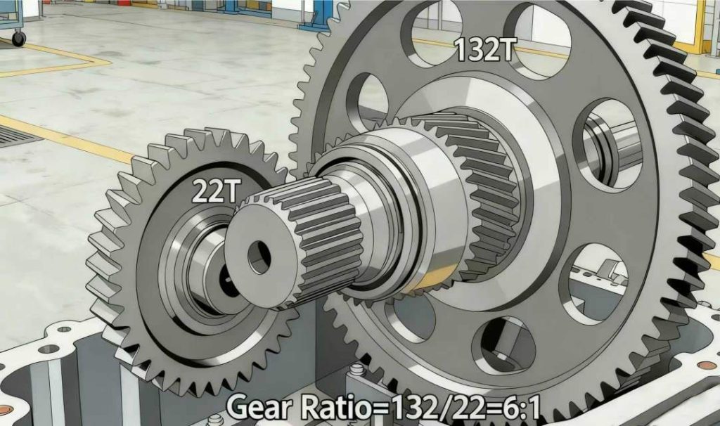
Method 1: Count the Teeth on Meshing Gears
When a gearbox is opened for inspection or repair, counting the teeth on the driving and driven gears is the most accurate way to determine the gear ratio.
Formula:
Gear Ratio = Number of Teeth on Driven Gear ÷ Number of Teeth on Driving Gear
Example – Conveyor Drive:
During a scheduled overhaul of a belt conveyor reducer, a technician counts:
- Driving gear (pinion): 22 teeth
- Driven gear (bull gear): 132 teeth
Gear Ratio = 132 ÷ 22 = 6:1
This means the input shaft rotates 6 times for every 1 full turn of the output shaft—delivering high torque at low speed.
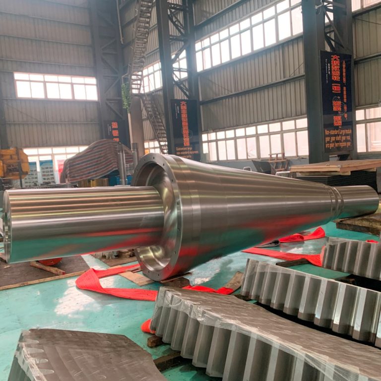
Best For: Open gearing, large industrial reducers (e.g., ZSY, DCY series), mill pinion and ring gear sets.
Method 2: Measure Input and Output Shaft Speeds
When disassembly isn’t possible, measuring rotational speeds offers a reliable way to determine the actual gear ratio while the equipment is running.
Formula:
Gear Ratio = Input Shaft RPM ÷ Output Shaft RPM
Step-by-Step Process:
- Use a handheld tachometer or laser RPM gun.
- Mark a reference point on both input and output shafts.
- Run the equipment at normal operating speed.
- Record the input RPM (from motor or coupling side).
- Record the output RPM (from drum, sprocket, or output flange).
- Divide input RPM by output RPM to get the effective gear ratio.
Real-World Example – Crusher Drive:
Motor speed: 1480 RPM
Crusher shaft speed: 296 RPM
Gear Ratio = 1480 ÷ 296 ≈ 5:1
This matches the expected reduction for a standard single-stage industrial gearbox.
Best For: Sealed gearboxes, in-service checks, conveyor drives, and pump units.
Method 3: Check the Nameplate or Manufacturer’s Manual
Most original equipment manufacturers clearly label the nominal gear ratio on the gearbox nameplate or in technical documentation.
Common formats include:
- “Ratio: 31.5:1”
- “i = 40”
- Model codes like “DBY355–28” where “28” indicates the speed ratio
Keep a physical or digital copy of equipment manuals on site. Search using:
- “[Equipment Model] + gear ratio”
- “[Manufacturer Name] + reducer catalog”
- “[Gearbox Type] + technical data”
Many suppliers provide downloadable catalogs with full specifications, including standard ratios.
Best For: Standardized mining gearboxes (e.g., SEW, Flender, domestic brands), spare part replacements, and procurement.
Common Mining Equipment and Typical Gear Ratios
| Equipment | Typical Gear Ratio Range | Notes |
|---|---|---|
| Belt Conveyors | 20:1 – 60:1 | Helical or planetary reducers; high starting torque needed |
| Jaw Crushers | 15:1 – 30:1 | Must handle impact loads; often use V-belts or direct gear drives |
| Ball/Rod Mills | 10:1 – 20:1 | Ring gear driven by pinion; ratio = ring gear teeth ÷ pinion teeth |
| Scraper Conveyors | 40:1 – 100:1 | Multi-stage planetary reducers common in underground setups |
| Hoists & Winches | 30:1 – 80:1 | High reduction for controlled lifting and lowering |
Always verify the total ratio in multi-stage gearboxes by multiplying the ratios of each stage.
Practical Tips for Mining Maintenance Teams
1.Account for Multiple Stages: Most industrial gearboxes have two or three reduction stages. Total ratio = Stage 1 × Stage 2 × Stage 3.
2.Include External Drives: If there’s a belt or chain drive after the gearbox, include its ratio in the total reduction.
3.Check for Wear: Worn gears may slip or have inconsistent meshing, leading to inaccurate RPM readings. Compare with design values.
4.Match Replacement Units Exactly: When replacing a gearbox, confirm the new unit has the same gear ratio—even a small difference can cause motor overload or coupling damage.
Improve Reliability: Keep a Gear Ratio Record
Maintenance teams should maintain a Log for critical equipment. Include:
- Equipment ID and location
- Motor RPM and power rating
- Gearbox model and nominal ratio
- Measured input/output speeds
- Date of last check
- Photos of nameplates or gear markings
This log supports faster troubleshooting, better spare part planning, and smoother handovers between shifts.
Know Your Gear Ratio, Protect Your Equipment
In mining, where equipment runs 24/7 under harsh conditions, small details make a big difference. Knowing how to find gear ratio ensures your drives are properly configured, reducing stress on motors, couplings, and gearboxes.
Use the methods in this guide—count teeth, measure speeds, or consult documentation—to maintain confidence in your mechanical systems.
Print it, post it in the maintenance office, and make it part of your team’s standard practice.

-768x768.jpg)