
Large Gear Wheel Manufacturing: Heavy-Duty Mining Solutions
Gear wheel are extensively used in various types of machinery and manufacturing equipment to transmit power and control the speed of different components.
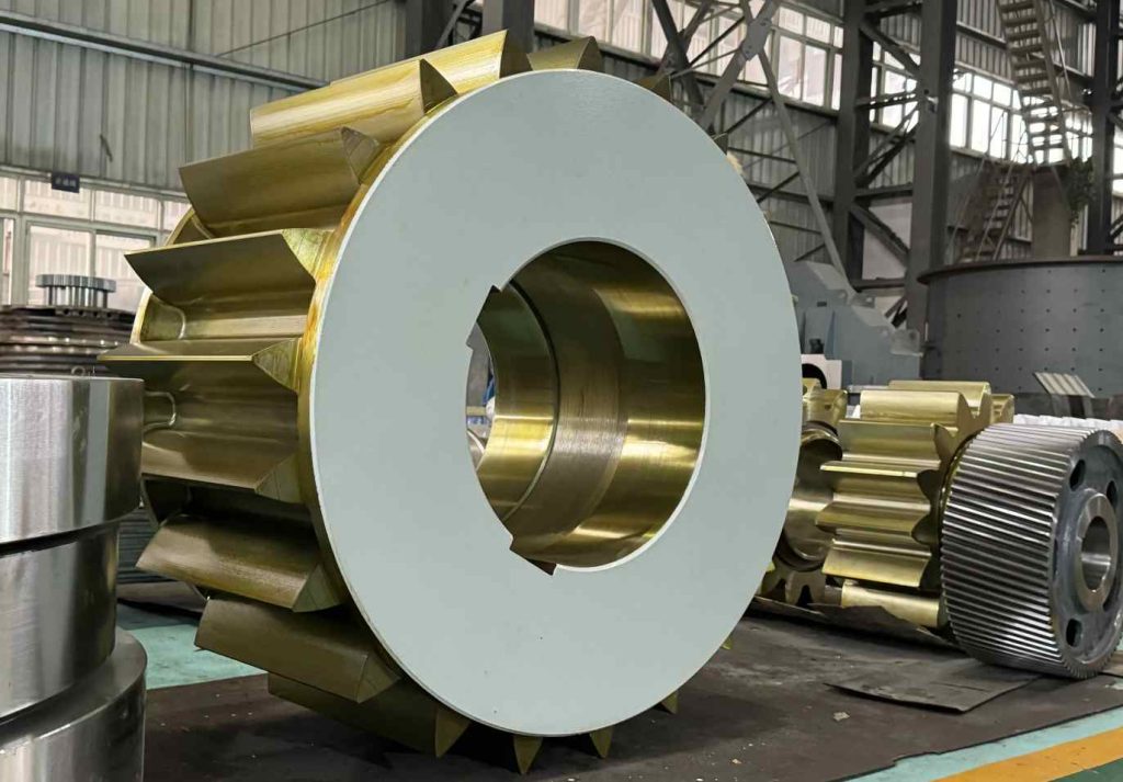
GEAR
1.Key Applications in Mining Equipment
Large industrial gears are indispensable in heavy-duty mining machinery, where they ensure reliable power transmission under extreme loads and harsh conditions. Below are critical applications:
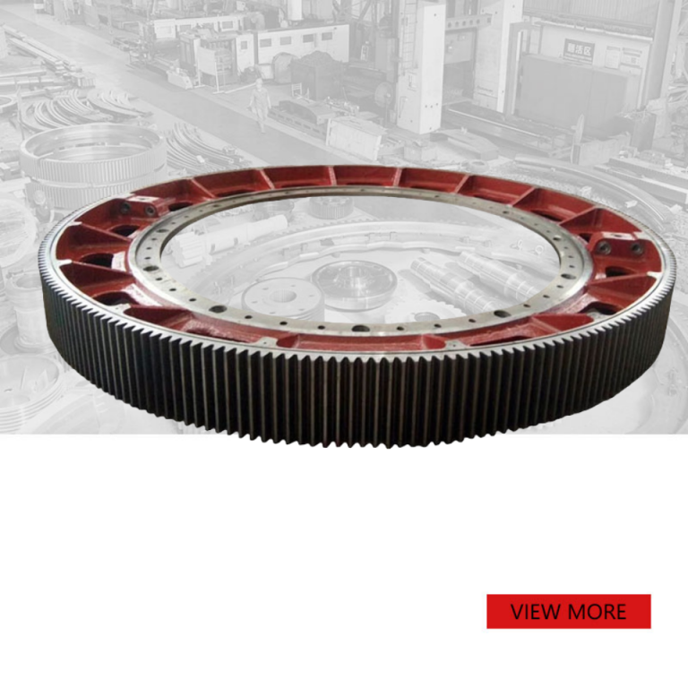
1.1 Ball Mills
Gear Type: Large ring gear
Material: 17CrNiMo6 alloy or custom
1.2. Jaw Crushers
Gear Type: Pinion gears
Material: Hardened 40CrNi or custom
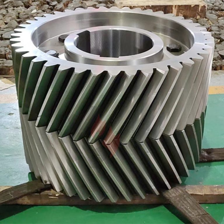
1.3. Rotary Kilns
Gear Type: Helical gear
Material: 17CrNiMo6 orcustom
1.4. Heavy-Duty Excavators
Gear Type: Slew gears and drive gears
Material: Forged 40Cr or custom
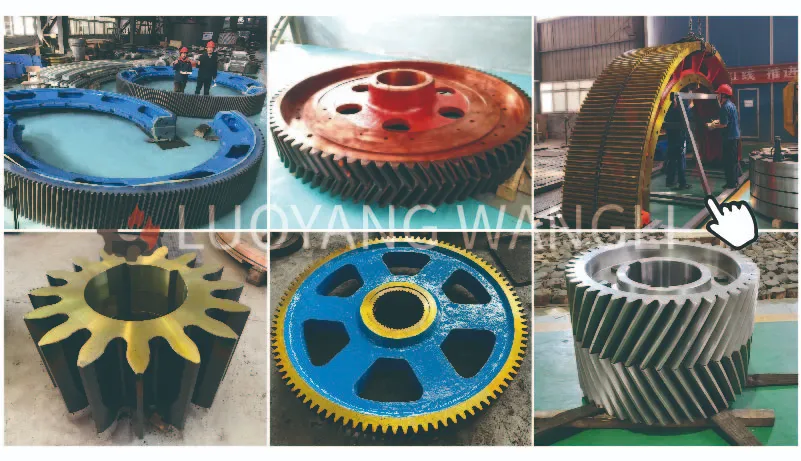
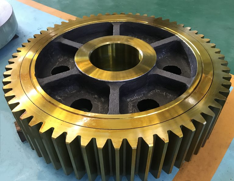
Various types of gears
2.Materials for Large Gear Wheel Manufacturing
| Material Type | Typical Applications | Hardness Range | Production Advantages | Production Limitations |
|---|---|---|---|---|
| Cast Steel (ZG45/ZG55) | Mining equipment spare parts (diameter >400mm) Ball mill ring gears Cement kiln drives | 156–229 HBS | • 20% lower cost vs. forged steel • No forging constraints for large diameters • Proven in 2,100+ mine spare parts | • Lower fatigue strength vs. forged steel • Requires 2-stage heat treatment (normalizing + tempering) |
| Forged Steel (40Cr/40CrNi) | Jaw crusher pinions Conveyor drive gears Rotary kiln helical gears | 201–269 HBS | • 35% higher fatigue resistance • Consistent hardness (±0.5 HRC in production batches) • Used in 1,200+ units/year for mining spares | • Higher raw material cost • Limited to diameters ≤400mm (forging constraints) |
| Hardened Alloy Steel (17CrNiMo6) | Critical spare parts (ball mills, heavy crushers) High-impact mining applications | 48–55 HRC (surface) 250–300 HBW (core) | • 5-year lifespan (vs. 2 years for standard steel) • Vacuum carburizing ensures uniform hardness layer (≥2.5mm) • 40% higher impact resistance | • 30% higher production cost • Requires 3-stage heat treatment (carburizing → quenching → tempering) |
| Cast Iron (HT250) | Low-speed conveyor drives Light-duty auxiliary equipment | 185–304 HBS | • Lowest production cost (45% below steel) • Excellent vibration damping • Suitable for non-critical spare parts | • 15% lower wear resistance (vs. hardened steel) • Unsuitable for mining equipment >500kW |
3.Common Issues and Solutions for Gear Wheel
3.1 Gear Wear and Fatigue Failure
Problem:
Pitting, spalling, or excessive wear on tooth surfaces reduce transmission efficiency and increase noise.
Causes:
- Insufficient material hardness (e.g., using standard carbon steel instead of 17CrNiMo6 alloy)
- Poor lubrication or incorrect lubricant selection
- Overloading or frequent impact loads
- Manufacturing inaccuracies (e.g., excessive tooth profile errors)
Solutions:
- Material Upgrade: Use 17CrNiMo6 alloy (carburizing treatment, hardness uniformity ±0.5 HRC).
- Lubrication Optimization: Apply high-viscosity gear oil and replace every 2,000 hours.
- Load Management: Ensure equipment operates within rated load limits.
- Precision Control: Maintain ±0.03mm tolerance during manufacturing .
3.2 Gear Tooth Fracture
Problem:
Tooth root or tip fracture causes complete transmission system failure.
Causes:
- Stress concentration in gear design (e.g., small fillet radius at tooth root)
- Internal material defects (e.g., inclusions, porosity)
- Severe overloading or impact loads
- Improper heat treatment (e.g., uneven quenching)
Solutions:
- Design Optimization: Increase fillet radius at tooth root to reduce stress concentration.
- Material Inspection: Use non-destructive testing (e.g., ultrasonic flaw detection) to ensure material quality.
- Load Monitoring: Install torque sensors to prevent overloading.
- Heat Treatment Improvement: Apply vacuum carburizing to ensure hardness uniformity (±0.5 HRC).
3.3 Excessive Gear Noise
Problem:
Abnormal noise during operation affects equipment performance and working environments.
Causes:
- Large tooth profile errors
- Misaligned gear axes
- Excessive or insufficient backlash
- Poor gear-to-bearing fit
Solutions:
- Precision Enhancement: Upgrade gear cutting accuracy to ISO 3-grade (tooth profile error ≤0.05mm).
- Installation Calibration: Use laser alignment to ensure parallelism (error ≤0.02mm).
- Backlash Adjustment: Adjust tooth clearance to 0.1–0.3mm as per equipment requirements.
- Bearing Inspection: Regularly check bearing clearance for optimal gear alignment.
3.4 Gear Overheating
Problem:
Abnormal temperature rise leads to lubrication failure and accelerated wear.
Causes:
- Inadequate lubrication or degraded oil
- Poor gear meshing (e.g., large tooth profile errors)
- Cooling system failure
- Excessive load operation
Solutions:
- Lubrication System Upgrade: Install forced lubrication systems for full gear coverage.
- Meshing Inspection: Check contact patterns regularly to ensure proper meshing.
- Cooling Maintenance: Ensure oil coolers function properly and clean regularly.
- Load Monitoring: Install temperature sensors for real-time monitoring.
3.5 Gear Thermal Deformation
Problem:
Dimensional changes during prolonged operation cause meshing issues.
Causes:
- Uneven heat treatment
- Excessive operating temperatures
- High material thermal expansion coefficient
- Poor structural design
Solutions:
- Heat Treatment Optimization: Use vacuum carburizing to limit thermal deformation ≤0.05mm.
- Material Selection: Use low-thermal-expansion alloys (e.g., 17CrNiMo6).
- Design Improvement: Add heat-dissipation grooves to gear structures.
- Operation Control: Set temperature limits to avoid prolonged overheating.
3.6 Gear-to-Shaft Fit Loosening
Problem:
Gap between gear and shaft causes imprecise transmission and vibration.
Causes:
- Insufficient interference fit
- Shaft or bore deformation
- Improper installation
- Thermal expansion mismatch
Solutions:
- Fit Optimization: Use H7/k6 or H7/m6 interference fit.
- Bore Machining: Ensure bore roundness and position tolerance ≤0.02mm.
- Installation Process: Use hydraulic tools to avoid impact damage.
- Thermal Assembly: Heat-treat gears post-processing to eliminate thermal expansion differences.
4.Preventive Maintenance Recommendations
- Regular Inspection: Check gear wear every 500 hours.
- Lubrication Management: Replace lubricant every 2,000 hours.
- Vibration Monitoring: Install sensors to detect anomalies early.
- Data Logging: Maintain gear operation records for failure analysis.
- Spare Parts Inventory: Stock critical gear spares to minimize downtime.
Following the implementation of the above preventive measures, the gear failure rate was reduced by 50%, and the equipment’s mean time between failures (MTBF) was extended to 4,100 hours.
Feel free to contact us for more information or assistance.
Our LinkedIn Page